Lecture: Geometric Modeling
Dear students:
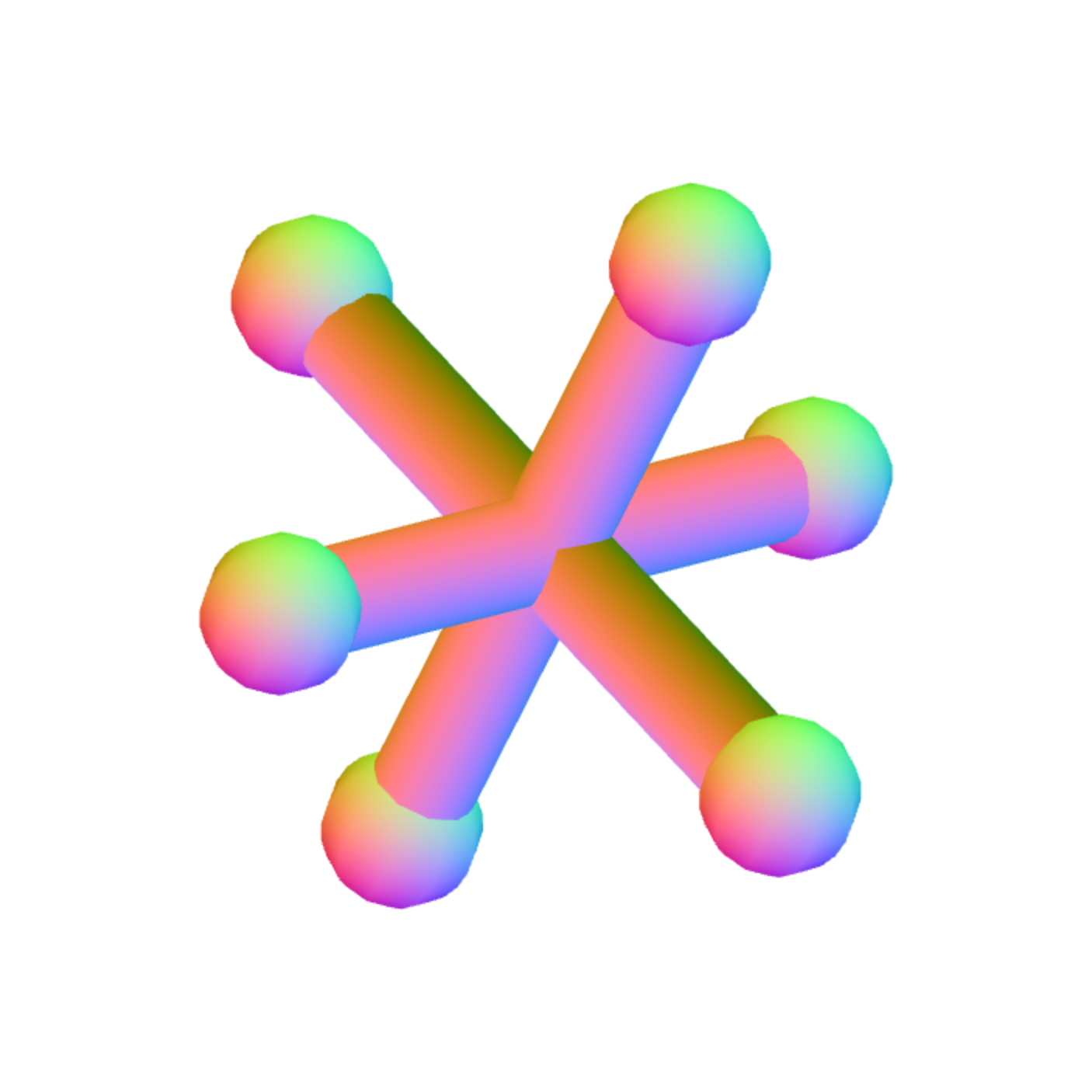
Our goal today is to generate a few models using code. The algorithmic description of shapes is sometimes called geometric modeling. Not all models can be easily generated via algorithms, and we are likely to build most of our models in a 3D modeling program rather than in code. However, programmatically generating shapes is instructive. It helps us develop an intimacy with the structure of a model. Today we will become intimate with a plane, a cylinder, and a sphere as we assemble this jack-like shape:
Plane
We've seen how to model a single quadrilateral with two separate triangles or four indexed vertices. Quadrilaterals are useful for modeling walls or floors. But what if we want a surface that isn't so flat? We need to decimate that quadrilateral into a quilt of quadrilaterals. We'll call this shape a plane. A mathematical plane goes on forever. Our plane will be bounded.
The table or grid of points of the plane can be generated with a couple of loops:
function generatePlane(width, height, nlatitudes, nlongitudes)
  positions = []

  for longitudeIndex through nlongitudes
    x = longitudeIndex / (nlongitudes - 1) * width - width * 0.5
    for latitudeIndex through nlatitudes
      y = latitudeIndex / (nlatitudes - 1) * height - height * 0.5
      positions.push(x, y, 0)

  return {positions}
}
function generatePlane(width, height, nlatitudes, nlongitudes)
positions = []
for longitudeIndex through nlongitudes
x = longitudeIndex / (nlongitudes - 1) * width - width * 0.5
for latitudeIndex through nlatitudes
y = latitudeIndex / (nlatitudes - 1) * height - height * 0.5
positions.push(x, y, 0)
return {positions}
}When we upload these to the GPU and render them as points, we see the intersection points of our grid. To fill in the pixels between these intersections, we have two choices: enumerate separate positions for each triangle, or use indexed geometry. Given that a single vertex may be shared by as many as six triangles, indexed geometry is a better choice.
Let's externalize our thinking about this grid with this diagram:

Given our algorithm above, what is the index of the vertex whose latitudeIndex is 0 and longitudeIndex is 0? That's vertex 0. How about the one whose latitudeIndex is 1 and longitudeIndex is 0? That's vertex 1. How about the one whose latitudeIndex is 1 and whose longitudeIndex is 0? That's vertex 4.
In general, we can determine the index through this formula:
function index(longitudeIndex, latitudeIndex)
  return longitudeIndex * nlatitudes + latitudeIndex
function index(longitudeIndex, latitudeIndex) return longitudeIndex * nlatitudes + latitudeIndex
Here's the complete list of indices:

We iterate through this table using a fencepost algorithm and issue index-triplets.
function generatePlane(width, height, nlatitudes, nlongitudes)
  // generate positions

  indices = []
  for longitudeIndex to nlongitudes - 1
    nextLongitudeIndex = longitudeIndex + 1

    for latitudeIndex to nlatitudes - 1
      nextLatitudeIndex = latitudeIndex + 1

      // Bottom-left triangle
      indices.push([
        index(latitudeIndex, longitudeIndex),
        index(latitudeIndex, nextLongitudeIndex),
        index(nextLatitudeIndex, longitudeIndex),
      ])

      // Top-right triangle
      indices.push([
        index(latitudeIndex, nextLongitudeIndex),
        index(nextLatitudeIndex, nextLongitudeIndex),
        index(nextLatitudeIndex, longitudeIndex),
      ])

  return {positions, indices}
function generatePlane(width, height, nlatitudes, nlongitudes)
// generate positions
indices = []
for longitudeIndex to nlongitudes - 1
nextLongitudeIndex = longitudeIndex + 1
for latitudeIndex to nlatitudes - 1
nextLatitudeIndex = latitudeIndex + 1
// Bottom-left triangle
indices.push([
index(latitudeIndex, longitudeIndex),
index(latitudeIndex, nextLongitudeIndex),
index(nextLatitudeIndex, longitudeIndex),
])
// Top-right triangle
indices.push([
index(latitudeIndex, nextLongitudeIndex),
index(nextLatitudeIndex, nextLongitudeIndex),
index(nextLatitudeIndex, longitudeIndex),
])
return {positions, indices}When we render this, our grid is nicely filled. But it doesn't look any different than a simple quadrilateral. We add some extra details to the internal vertices, like random colors:
function generatePlane(width, height, nlatitudes, nlongitudes)
  positions = []
  colors = []

  for longitudeIndex in nlongitudes
    x = longitudeIndex / nlongitudes * width - width * 0.5
    for latitudeIndex in nlatitudes
      y = latitudeIndex / nlatitudes * height - height * 0.5
      positions.push(x, y, 0)
      colors.push(random(), random(), random())

  // generate indices

  return {positions, colors, indices}
function generatePlane(width, height, nlatitudes, nlongitudes)
positions = []
colors = []
for longitudeIndex in nlongitudes
x = longitudeIndex / nlongitudes * width - width * 0.5
for latitudeIndex in nlatitudes
y = latitudeIndex / nlatitudes * height - height * 0.5
positions.push(x, y, 0)
colors.push(random(), random(), random())
// generate indices
return {positions, colors, indices}Perturbing the positions is also possible. That's how we'd generate terrain, which seems to be a rite of passage for every budding graphics developer.
To shade the plane, we need a normal at each vertex. Since the plane is flat, the normals all point the same direction. It feels silly to make this uniform normal an attribute, but we do it anyway, to prepare for less flat geometry:
function generatePlane(width, height, nlatitudes, nlongitudes)
  positions = []
  colors = []
  normals = []

  for longitudeIndex in nlongitudes
    x = longitudeIndex / nlongitudes * width - width * 0.5
    for latitudeIndex in nlatitudes
      y = latitudeIndex / nlatitudes * height - height * 0.5
      positions.push(x, y, 0)
      colors.push(random(), random(), random())
      normals.push(0, 0, 1)

  // generate indices

  return {positions, colors, normals, indices}
function generatePlane(width, height, nlatitudes, nlongitudes)
positions = []
colors = []
normals = []
for longitudeIndex in nlongitudes
x = longitudeIndex / nlongitudes * width - width * 0.5
for latitudeIndex in nlatitudes
y = latitudeIndex / nlatitudes * height - height * 0.5
positions.push(x, y, 0)
colors.push(random(), random(), random())
normals.push(0, 0, 1)
// generate indices
return {positions, colors, normals, indices}Cylinder
A plane is flat. We now generate a shape that's a little bit round: a cylinder. We take the longitude as a proportion
function generateCylinder(radius, height, nlatitudes, nlongitudes)
  positions = []
  for longitudeIndex to nlongitudes
    radians = longitudeIndex / nlongitudes * 2 * pi
    x = radius * cos radians
    z = radius * sin radians
    for latitudeIndex to nlatitudes
      y = latitudeIndex / (nlatitudes - 1) * height - 0.5 * height
      positions.push(x, y, z)
      normals.push(cos radians, 0, sin radians)

  // generate indices

  return {positions, normals, indices}
function generateCylinder(radius, height, nlatitudes, nlongitudes)
positions = []
for longitudeIndex to nlongitudes
radians = longitudeIndex / nlongitudes * 2 * pi
x = radius * cos radians
z = radius * sin radians
for latitudeIndex to nlatitudes
y = latitudeIndex / (nlatitudes - 1) * height - 0.5 * height
positions.push(x, y, z)
normals.push(cos radians, 0, sin radians)
// generate indices
return {positions, normals, indices}The normals point in the same direction as the vertices from the y-axis.
We draw this cylinder three times under differ rotation matrices to form the studs of the jack.
Sphere
Generating a sphere is surprisingly like generating a plane or a cylinder. They are shaped very differently, of course, but their faces are not connected differently. We can use very similar code to generate the indices. We start with the positions.
To calculate the positions, we could look up the parametric equations for a sphere, but we're going to take a different approach that I think feels less like magic. We first sample the right half of a circle in the z = 0 plane, starting at -90 degrees at the bottom of the circle and working our way up to 90 degrees at the top. This gives us a set of seed points at various latitudes:
function generateSphere(nlatitudes, nlongitudes)
  seeds = []
  for latitudeIndex to nlatitudes
    radians = latitudeIndex / (nlatitudes - 1) * pi - pi / 2
    seeds.append([cos radians, sin radians, 0])
  // ...
function generateSphere(nlatitudes, nlongitudes)
seeds = []
for latitudeIndex to nlatitudes
radians = latitudeIndex / (nlatitudes - 1) * pi - pi / 2
seeds.append([cos radians, sin radians, 0])
// ...Then we spin these seed points around the y-axis to produce lines of longitude:
function generateSphere(nlatitudes, nlongitudes)
  // generate seeds

  positions = []
  normals = []
  for longitudeIndex to nlongitudes
    degrees = longitudeIndex / nlongitudes * 360
    rotation = Matrix4.rotateY(degrees)
    for latitudeIndex to nlatitudes
      position = rotation * seeds[latitudeIndex]
      positions.push(position)
      normals.push(position)

  return positions
function generateSphere(nlatitudes, nlongitudes)
// generate seeds
positions = []
normals = []
for longitudeIndex to nlongitudes
degrees = longitudeIndex / nlongitudes * 360
rotation = Matrix4.rotateY(degrees)
for latitudeIndex to nlatitudes
position = rotation * seeds[latitudeIndex]
positions.push(position)
normals.push(position)
return positionsWhen we render these positions as points, we see what looks like a globe. We can connect these points together exactly as we did for the plane. However, we want the last line of longitude to wrap around connect back to the first. A little modulus can help make that happen:
for longitudeIndex to nlongitudes
  nextLongitudeIndex = (longitudeIndex + 1) % nlongitudes
  ...
for longitudeIndex to nlongitudes nextLongitudeIndex = (longitudeIndex + 1) % nlongitudes ...
We add these positions and indices to our vertex buffer objects and we have a filled sphere. With some help from translation matrices, we place six spheres at the endpoints of the studs.
Rotation
Now that we have a real 3D object, it'd be nice to take it for a spin. Let's use the cursor keys to rotate the object up, down, left, or right. First we need a mouse listener, which we register in the initialize function:
window.addEventListener('keydown', event => {
  if (event.key === 'ArrowUp') {
    // ...
  } else if (event.key === 'ArrowDown') {
    // ...
  } else if (event.key === 'ArrowLeft') {
    // ...
  } else if (event.key === 'ArrowRight') {
    // ...
  }
});
window.addEventListener('keydown', event => {
if (event.key === 'ArrowUp') {
// ...
} else if (event.key === 'ArrowDown') {
// ...
} else if (event.key === 'ArrowLeft') {
// ...
} else if (event.key === 'ArrowRight') {
// ...
}
});We also track the accumulated rotation up in a matrix global. On each cursor keypress, we tack the desired rotation on to the accumulated rotation:
spin = Matrix4.rotateX(3).multiplyMatrix(spin);spin = Matrix4.rotateX(3).multiplyMatrix(spin);
Then at draw time we combine the global rotation with the transformation applied to each piece of the jack:
worldFromModel = spin.multiplyMatrix(place);worldFromModel = spin.multiplyMatrix(place);
That gives us a spinning jack.
TODO
Here's your TODO list:
See you next time.
Sincerely,
