Perspective Projection
In order for a rendered scene to feel real, we must simulate how light passes through the scene and into the human eye. One important quality of reality is that objects farther from the eye appear smaller than those near. Orthographic projections do not scale objects according to their depth. For that, we need a perspective projection.
Human Vision and Computer Graphics
Some ancient Greek thinkers held the theory that a creature's eyes emitted light into the environment. When eyes are open, near objects are illuminated. If the light rays are blocked by blinking eyelids or other objects, objects are dark. These days, we understand that photons are emitted from light sources and hit the surfaces of the world. Some photons are absorbed into the surfaces, some are reflected away from the surfaces, and some are refracted through the surfaces. Which of these three behaviors occurs depends on the frequency of the light and the material properties of the surfaces.
Some of the non-absorbed light bounces into our eye, passing through the lens at its front. Real lenses have apertures that expand and contract to control how much light enters. In computer graphics, we assume the lens of the simulated eye is very small, the size of a pinhole. The photons land on nerve cells at the back of the eye. This collection of cells is called the retina in a real human eye and an image plane in computer graphics.
We can figure out where a photon from an object will land on the retina by drawing a line from the object through the lens of the eye. If we extend the line into the eye, we find that photons coming from below the eye pass through and land at the top of the retina, while photons from above land at the bottom. This means that the retina receives a picture of the world that is upside down. Here the retina receives an upside-down image of the tree:
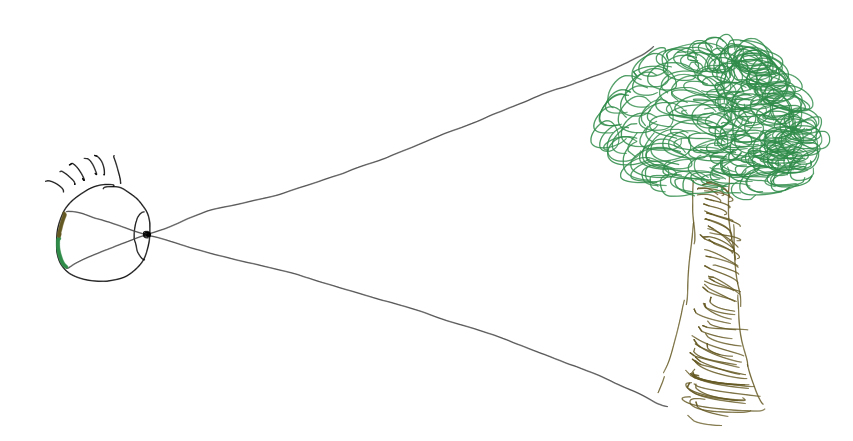
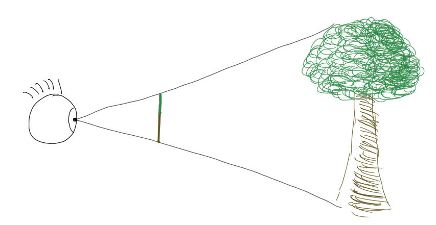
Though image flipping is a physiological reality, it is not a phenomenon we need to mimic in our renderers. In computer graphics, we move the image plane from behind the lens to in front of the lens, where computations will be easier. When light projects onto an image plane in front of the viewer, the projected image is upside up.
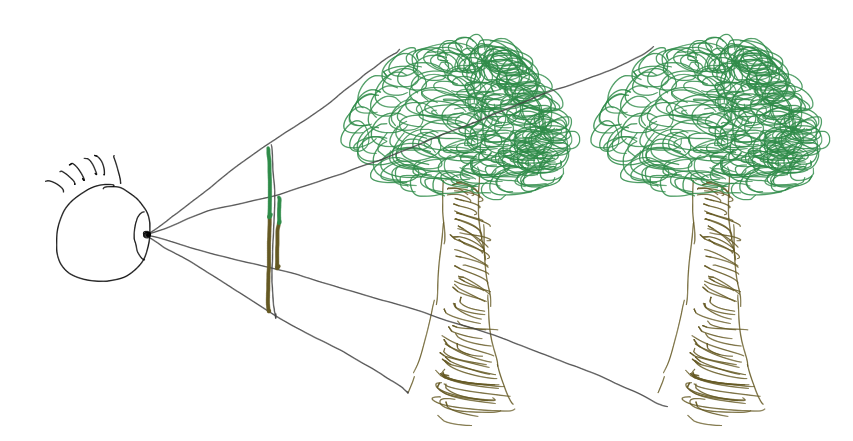
Photons from an object that is farther away will have rays with smaller slopes than photons from a closer object of the same size, and the farther object will therefore project to a smaller area of the image plane. That geometric effect is what we call perspective.
To simulate how light projects this flattened perspective view of the world on the retina, we will need to do some math.
Viewing Frustum
In an orthographic projection, light does not converge onto an image plane. There's no notion of a lens funneling light through a pinhole. The viewing volume is a box, and photons travel in parallel rays through the world and land at perpendicular angles on the image plane.
In a perspective projection, light does pass through a lens, which filters out only the rays that happen to bounce from the objects through the lens. The chunk of the world that is seen is not a box, but rather a pyramid. Many graphics libraries expect us to shape this pyramid through the following four parameters:
- The vertical field of view. How many degrees tall is the pyramid?
- The aspect ratio. What is the pyramid's width-to-height ratio?
- The near distance. At what point distance does the eye start perceiving?
- The far distance. At what point distance does the eye stop perceiving?
The pyramid is artificially truncated by the near and far distances, making it a frustum. Explore how the viewing frustum of a perspective projection is shaped by these four parameters:
To get perspective in our own renderers, we must carve out a frustum in eye space and then figure out how to squeeze it into the unit cube that WebGL expects. Mapping the orthographic projection's rectangular prism to a unit cube requires just a translation and a scaling. Mapping a pyramid is lot more work.
Our first step is to decide that the image plane will be on the front face of the frustum. Light will pass from the frustum on its way to the eye and collect on that face. We need to find out exactly where it will land. The four frustum parameters give us all the information we need figure that out. Consider this side profile of the frustum in eye space:
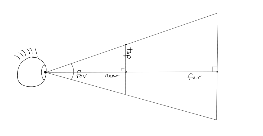
See the near and far clipping planes? See how the field of view controls the vertical aperture? See the right triangle formed at the top-left quadrant? Since we know the angle of this triangle at the eye (\(\frac{\mathrm{fov}_y}{2}\)) and the length of the adjacent side (\(\mathrm{near}\)), we can use a little trigonometry to determine the value \(\mathrm{top}\), which is the y-coordinate of image plane's top:
We now know where the top of the image plane is. How wide is it? We know the frustum's aspect ratio, which relates its width and height:
The parameters \(\mathrm{near}\), \(\mathrm{far}\), \(\mathrm{top}\), and \(\mathrm{right}\) are what we'll use to build a perspective projection matrix.
Plane Projection
With our frustum and image plane defined, we are ready to figure out where on the plane each vertex projects. Let's call the vertex's eye space position \(\mathbf{p}_\mathrm{eye}\). We want the projected position \(\mathbf{p}_\mathrm{plane}\):
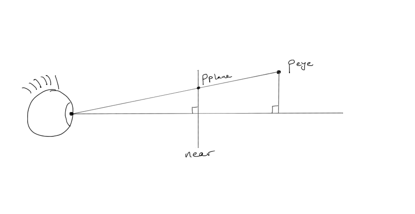
The vertex sends its photons to the eye, projecting from eye space onto the image plane. The x- and y-coordinates of the projected vertex are calculated with the help of the two similar triangles shown in this figure. We know the z-coordinate of the projected position:
It's negative because this is eye space, in which the viewer is looking from the origin down the negative z-axis.
The y-coordinate we figure out by setting up similar triangles. Since the triangles are similar, the ratio of their side lengths must match. Using the components from our two positions, we have these similar ratios:
To simplify future steps, let's flip the signs of the denominators:
We solve for \(y_\mathrm{plane}\):
The x-component is computed similarly:
Normalized Coordinates
We have the equations to turn an arbitrary eye space position into a position on the image plane. That's great, but what we really need is a matrix that turns the frustum into the unit cube of normalized space. We want coordinates at the top of the frustum to map to 1 on the normalized y-axis. We want coordinates at the right of the frustum to map to 1 on the normalized x-axis.
To normalize our plane coordinates, we divide them by the \(\mathrm{top}\) and \(\mathrm{right}\) values we derived earlier:
We're going to ignore \(z_\mathrm{normalized}\) for the moment because it's messy.
Matrix and Perspective Divide
The transformation pipeline is built around matrices. We want to build a perspective matrix that transforms our eye space coordinates into normalized coordinates. In particular, we want this to happen:
What row when dotted with the eye space position will produce \(x_\mathrm{normalized}\), the first component of the product? None. It's not possible to bring both \(x_\mathrm{eye}\) and \(z_\mathrm{eye}\) into the same term with a dot product. Just as we saw with translation, it appears that matrix multiplication may not work for what we're trying to do.
Never fear. The graphics card designers snuck an extra step into the graphics pipeline so that we can render models in perspective using a matrix multiplication. They decided that instead of targeting normalized space directly, we will target an intermediate space called clip space. In clip space, the coordinates have not been divided by \(-z_\mathrm{eye}\). After we emit a position in this undivided clip space, the card will divide all components of the position by the value that appears in the position's homogeneous coordinate. Since our normalized coordinates have \(-z_\mathrm{eye}\) in their denominator, that's the value we want as our homogeneous coordinate.
The division by the homogeneous coordinate is called the perspective divide. This divide lands us at the normalized coordinates we want:
With \(-z_\mathrm{eye}\) moved out of the way, we have this simpler transformation to achieve:
A few rows of the matrix fall out quickly. The x- and y-components are just scales, and the bottom row must select out and negate the z-component to form the correct homogeneous coordinate:
We have now constructed 75% of the matrix. The third row won't give itself up so easily.
Third Row
The job of the third row of the perspective matrix is to compute \(z_\mathrm{clip}\) as this dot product:
We must reason out what the unknowns should be. A vertex's \(z_\mathrm{clip}\) does not depend on the eye space x- or y-coordinates, so we zero them out:
The values of the other two unknowns are less obvious. Let's name them so we can do some algebra:
Now we expand the dot product:
Let's also manually apply the perspective divide so that we move from clip space into normalized space:
The two unknowns are still unknown. However, we have a couple of mathematical truths in our back pocket that will help us resolve them. First, because we are mapping to the unit cube, we know what \(-\mathrm{near}\) and \(-\mathrm{far}\) should map to:
Two equations with two unknowns form a linear system that we can solve. We solve the first equation for \(b\):
We substitute this expression for \(b\) in our second equation and solve for \(a\):
Then we substitute this expression for \(a\) back into the equation for \(b\) and simplify:
Whew. That algebra plugs in the last two holes in our matrix. Altogether, our perspective transformation looks like this:
Likely we'll want to hide the complexity of building this matrix in a library routine that receives the frustum parameters.
Then a renderer can conjure up a frustum-squeezing transformation with a call like this:
const clipFromEye =
  Matrix4.perspective(fov, aspectRatio, near, far);
const clipFromEye = Matrix4.perspective(fov, aspectRatio, near, far);
Because we found a way to achieve perspective with a matrix, the vertex shader looks just as it did under an orthographic projection:
uniform mat4 worldFromModel;
uniform mat4 eyeFromWorld;
uniform mat4 clipFromEye;
in vec3 position;

void main() {
  gl_Position =
    clipFromEye * eyeFromWorld * worldFromModel * vec4(position, 1.0);
}
uniform mat4 worldFromModel;
uniform mat4 eyeFromWorld;
uniform mat4 clipFromEye;
in vec3 position;
void main() {
gl_Position =
clipFromEye * eyeFromWorld * worldFromModel * vec4(position, 1.0);
}After the vertex shader finishes, the graphics card will automatically perform the perspective divide, moving the vertex into normalized space.